Ground Loops
🌑︎ : Background
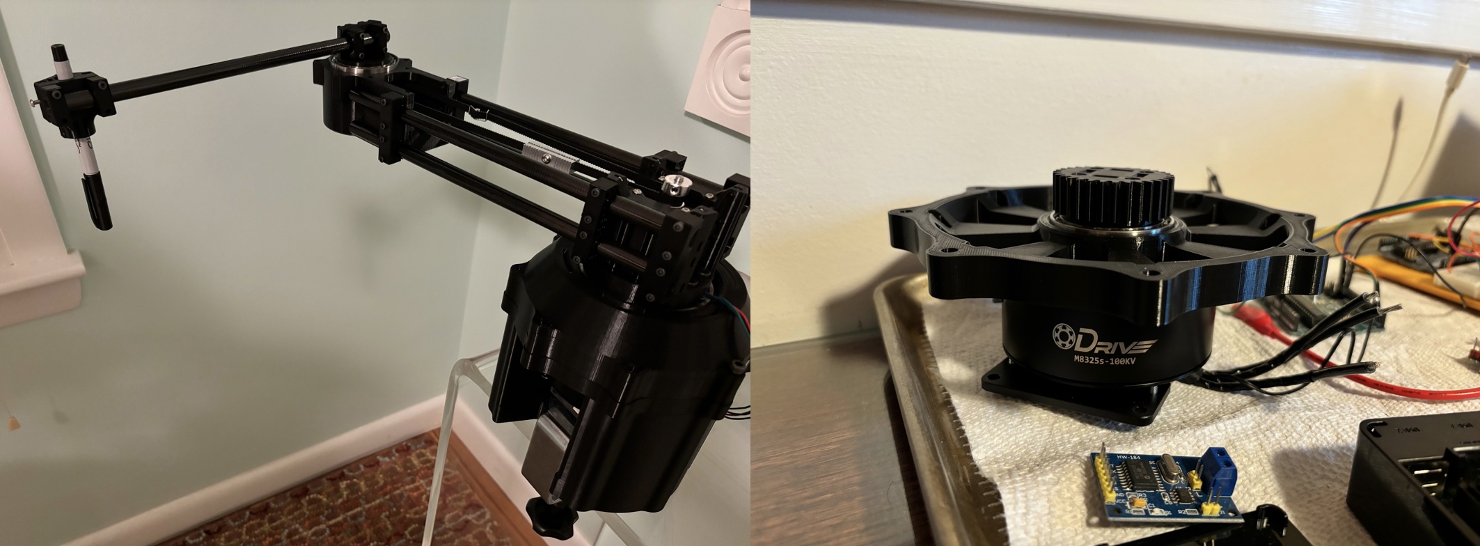
I’ve recently finished all the 3D prints for a robot arm. A M8325 ODrive actuates the shoulder and a plain NEMA17 stepper actuates the elbow. Eventually, I hope to add a quaternion wrist joint and have the arm intercept/hopefully return ping pong balls (tracked with stereo vision), but wanted to start with a smaller project scope.
The current goal is just to get this robot arm to draw simple shapes using differential inverse kinematics (with the help of Drake). I plan on using ros2_control and Odrive’s ROS2 CAN package to make interfaces for the RPi 5 to communicate with the ODrive and Arduino/TMC2209. The RPi will have a RS485 and the Arduino will have a MCP2515 for CAN communication.
Planning the wiring has been a bit more difficult than I expected because it has taken me some time to understand how to manage ground loops and electromagnetic interference (EMI). Below are some of the questions I have had, and hopefully their answers (thank you solomon!).
🌒︎ : Conceptual Questions
-
What are the different ways that current can flow through ground loops?
- Current will flow through a ground loop if the two grounds in the loop have different voltage levels (like with two different outlets).
- They can also generate new noisy current if AC current passes through them. The resulting magnetic field induces a current in the ground loop.
- Sources: Ball Systems
-
I’ve heard if you can draw a loop in your ground paths, you have a ground loop. How extreme is this? What if I have a hole in a busbar ground, is the path around the hole a ground loop? What if I need a thicker, lower AWG cable for ground, but instead just use two thinner cables that take the same path, is this a ground loop?
- Yes, those are both ground loops. But the severity of a ground loop depends on the area of the loop, difference in ground voltages, and whether other signals are carried on the wire.
- The size of the loop matters (see why). So because a hole in a busbar is pretty small, this isn’t going to generate a large current.
- What else is on the loop matters. Extra noise on a busbar and extra noise on two grounding cables probably isn’t a problem, since they aren’t sensitive to ground loop current. Ground loop current becomes a problem when it starts flowing through signal wires (like a USB connection), or pins on a board that aren’t able to handle the ground loop currents (this is why ODrive recommends if worst comes to worst and you have to have a ground loop, put resistors between the low current pins to protect them by limiting the ground loop current that can flow).
- The ground loops created by the layers of a PCB (vias connecting to the copper ground layer) have very small inductance since they are so small.
- Sources: SE Question
- Solomon from ODrive: “Yes this is all true, but usually when we’re talking about ground loops we’re talking about the ones that can potentially cause damage”
-
I’ve heard if you use two seperate outlets, your ground can be at two different potentials. How is this possible if the two outlet grounds both connect to the ground busbar at the breaker box? Additionally, at 2:30, Zach says the reason is because a voltage difference may exist between two outlet grounds is because there is an “stake in ground… imperfect connection… in the earth”. But don’t these two outlets meet at the ground busbar in the breaker box before the lightning rod?
- All wires have some impedance and resistance. So just because all outlets in a house meet at the same ground busbar, the wires don’t “teleport” this ground reference perfectly from the busbar to each outlet.
- Side note: never break off an outlet ground pin to prevent a ground loop between two devices. If the device has a fault, there is no high-current ground path for the current to take, only through the signal ground (the plug between the two devices), through the other devices power ground. This high current is likely to burn up the signal ground. With no low resistance path to take back to ground, this current may then flow through you.
- Sources: Audio Video,
- Solomon from ODrive: “Yes but you don’t care about AC ground typically, even power supplies usually don’t bond their DC- output to earth ground, we just use ground to mean 0V in a system”
-
Why does reducing the area of a ground loop reduce the amount of current that it induces?
\[\displaylines{ v = \frac{d\lambda}{dt} \\ \lambda = N \phi \\ \phi = \mathscr{P}Ni \\ \mathscr{P} = \frac{\mu A}{\mathcal{l}} \\ v = \frac{d\lambda}{dt} = \frac{d(N \phi)}{dt} = \frac{d(N\mathscr{P}Ni)}{dt} = N^2\mathscr{P}\frac{di}{dt} \\ v = L\frac{di}{dt} }\]-
TLDR: Because reducing the area is the same as reducing L. It reduces the area available for the flux to act on.
- \(\lambda\) is flux linkage, measured in weber-turns
- N is the number of turns of the inductor
- \(\phi\) is the flux, measured in webers
- \(\mathscr{P}\) is the permeance, and is dependent on the material and cross sectional area of the inductor. A larger cross-sectional area increases \(\mathscr{P}\), which increases the inductance L, which means for a given change in current, the voltage difference is larger.
- For ground loops, we want to avoid a large voltage difference (because this means more noisy current pushed through our ground loop), so keeping the cross-sectional area small helps with this.
-
-
What allows ODrive ferrite rings to allow motor current to pass, while also filtering out EMI/RFI? Is it because the motor current is lower frequency than the EMI, or because the motor current is differential mode (the current in all three phase wires adds up to 0), while EMI is common mode?
-
I think that both the common mode nature and effective frequency range of the ferrite rings allows it to both absorb EMI and ignore motor power
- Common Mode
- Common mode current is shared on all wires. It is the average current.
- Differential mode current cancels out on all wires. It is the difference between currents.
- If wire A is 3A, and wire B is -4A, the common mode current is -.5A and the differential mode current is 7A. Notice that…
- Because all 3 phase wires are wrapped in the same direction around the ferrite core, they induce magnetic fields in the same way. Therefore, because the total current for motor power across the 3 phase wires is 0, the magnetic fields will cancel out. Said another way, for differential mode current, the common mode choke acts like a short.
- In contrast, the EMI that travels in the same direction across all 3 phase wires does not cancel out, so the common mode choke impedes it.
- Motor EMI is common mode because it returns on all 3 phase wires from the motor.
- Motor power current is differential mode, since the amount of current entering and leaving the phase wires must equal 0 (not considering EMI).
- Sources: Video
- Frequency Range
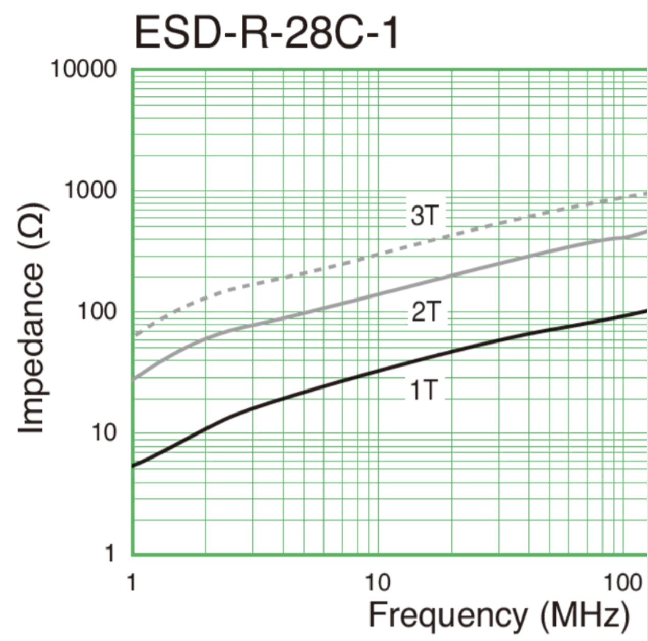
- Ferrite impedance rises with frequency (see image below from the ODrive product listing)
- Electromagnetic frequency (EMI) includes audio frequency (up to 20kHz), and radio frequency (RFI) (over 20kHz). So this ferrite ring seems to mainly affect medium frequency radio frequency (300kHz - 3MHz) and higher frequencies.
- I believe that the motor current frequency is much lower than any EMI frequency.
- Follow up question
- What creates the EMI/RFI in a motor? What frequency is the emitted interferance?
- At what current does an ODrive ferrite ring (wrapped around the phase wires) become necessary?
-
-
What is the difference between the two CAN IOs, pins 1-4, and RS485A/RS485B on the ODrive S1?
- The RS485 pins have nothing to do with RS485 CAN hats. They are a differential interface for RS-485 encoders.
- Solomon from ODrive: “The CAN on the big IO on the S1 and the side CAN connectors are the same, it just for ease of wiring ( daisy chaining on the side connectors makes wiring easy, but some people just want to have a single connector to their S1 instead). RS485 is different as you noted, that’s for RS485 encoders”
-
Why does ODrive say to keep the 2 Odrive power cables short and close together (to lower impedance)? If the current powering the ODrive via the 2 power cables is DC, why does impedance matter at all? Does PWM/FOC cause the current to constantly change at this input?
- Solomon from ODrive: Noted that this advice in the documentation might be incorrect.
-
What does this mean? “ODrive is happier with higher inductance… means current controller bandwidth is reduced”
- The motor torque and motor current are directly proportional (their ratio is the \(K_T\) motor constant)
- Therefore, if we want to use torque control for our motor, we can use current control.
-
current_controller_bandwidth sets the P and I terms of the PI current controller.
- Follow up questions
- How does higher impedance relate to reduced P and I terms?
- How does current control work? How can we increase the current going through the motor without having control of the torque applied to the motor? For example, if we wanted to increase the current through the motor by increasing the voltage, wouldn’t the motor just speed up and keep the same current (assuming no new load is applied)?
🌓 : Possible Circuit Layout
Wiring Questions
-
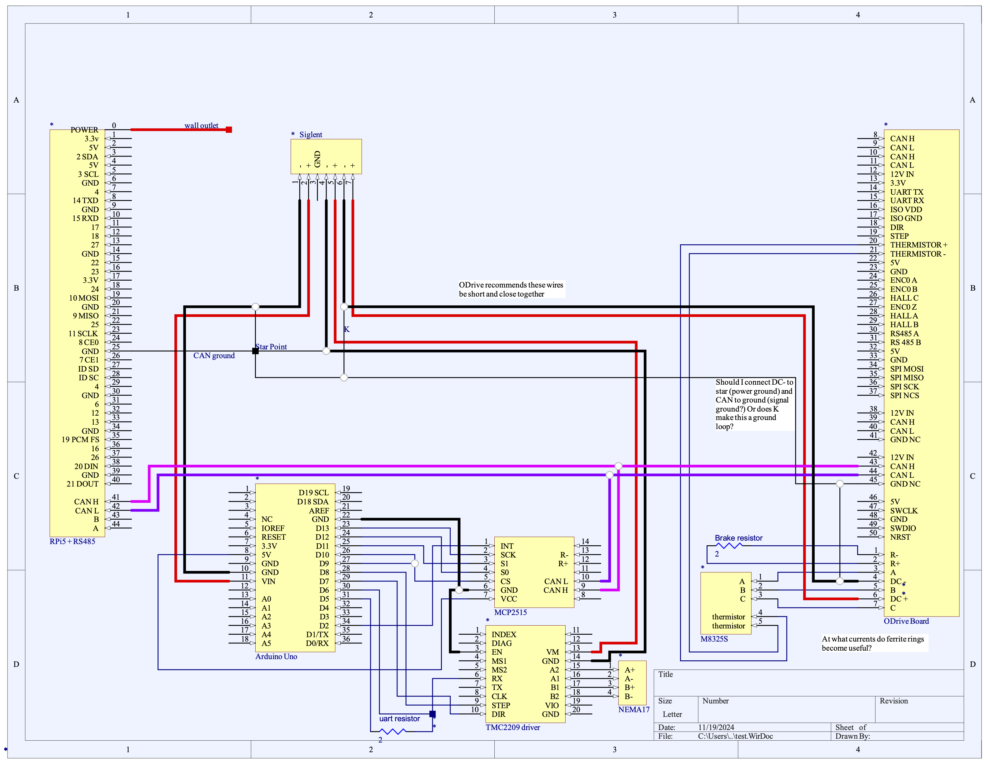
Is there any glaring issues with the harness, or simple improvements to make?
- Solomon from ODrive:
- “Can’t see anything obviously wrong. By “MCP2515” I’m assuming you mean a breakout board with both MCP2515+CAN transciever, and with the TMC2209 you’ll have some external bulk capacitance. Also not quite sure why you’re doing three Siglent channels, I’d probably just get a big chunky 24V supply and have a DC/DC for the Arduino and rPi”
- “My big recommendation is to just use a high quality Mean-Well supply and ring terminals, then it’s pretty damn safe”
- “TMC2209 bulk capacitance == just chuck a 220uF electrolytic with voltage rating » Vbus across VM/GND close to the stepper driver”
- Solomon from ODrive:
-
GND NC Pins. What is the point of CAN GND NC pin on the ODrive S1? The ODrive CAN Bus Guide says to reference it to DC- and not the CAN/Logic ground, while the ODrive Arduino CAN Guide seems to have it wired both to DC- ground and Arduino ground.
- “GNC NC offers a common connection for the CAN bus ground, it is not connected internally”
- “CAN referenced to DC- on ODrive S1. CAN GND not used.”
- On the ODrive S1, “CAN is not isolated, CAN signals are referenced to DC-. Therefore you must connect your CAN bus ground to DC- at the system star point.”
- The two CAN GND NC pins are not connected to the board’s DC-, and are only used for daisy chaining CAN ground without creating a ground loop through the ODrive S1.
- So should there always be a wire going from DC- to any CAN GNC NCs?
- If the CAN on an ODrive S1 isn’t isolated, isn’t it already referenced to DC-? Why are connections to the NC ports necessary?
- Solomon from ODrive: “So here the only thing you need to do is ensure there’s a single star point between the S1 DC-, the Arduino GND, and the rPi GND. GND NC isn’t internally connected on the S1, and is just a passthrough for ease of wiring in certain cases – so you don’t need to connect anything to it unless you’re using it as a passthrough between the two CAN JST-GH. I would use k but not bother with the tie between DC- and GND_NC right at the S1. In the arduino example, it’s just using the passthrough – you could remove the arduino GND to GND_NC and then the GND_NC to DC- tie and do this instead [referring to making a connection from the DC- terminal directly to star ground], and it would be strictly equivilant”
🌕︎ : Next Steps
- ros2_control
- drake
- circuit schematic with lipo?
🌗︎ : Junk Questions
- Can ground current flow through CAN HI and CAN LO to create a ground loop?
- When should I use the Siglent 3303 green ground terminal?
- Are the 3 Siglent 3303 power channels isolated from each other?
- I understand that inductors resist change in current and can’t change from one amperage to another immediately (because this would mean \(\frac{di}{dt} = \infty\) and therefore the voltage to achieve this would be infinite). But physically, why can’t they change immediately? Can magnetic fields not dissipate immediately?
- I’ve heard some suggestions that if you have two grounds with different voltage potentials, you can connect a large resistor between that allows about ~1mA to flow between them. How would this solve anything? If there is a large resistor, isn’t there still a voltage difference between the two.
- Why use PWM to simulate a lower voltage instead of just lower the input voltage? What is constant current reduction?
- Other notes
- Make sure that signal circuits are referenced to one point as ground (vid)